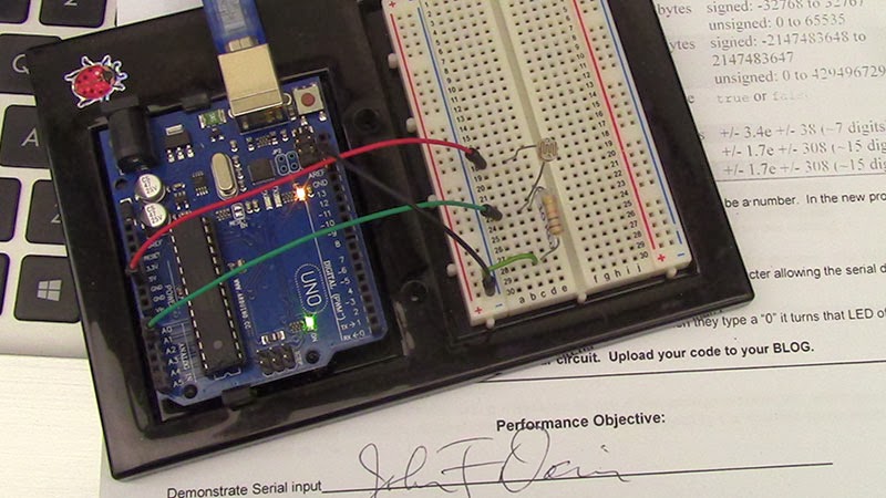
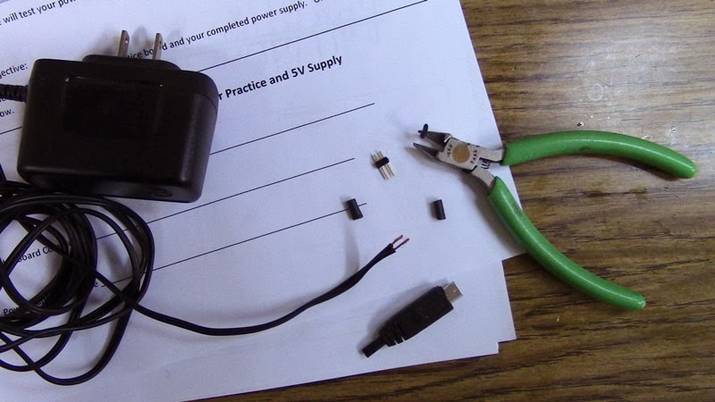
We had a very nice lecture and lab practice on how to use a multimeter this evening. We used a multimeter to measure continuity, resistance, voltage, current and capacitance, etc.
We used a multimeter to find out if two electronic parts are electrically connected. We used the solder board we soldered yesterday for practice. We only test continuity when the device is not powered so we can get the correct reading. Here are some examples of using a multimeter:
Testing electrical continuity:
Continuity is non-directional; it is the same how you place your probes on the device you are testing.
Testing Batteries:
We switched to DC mode when measuring batteries. Direct current voltage is what comes out of batteries.
Here is my 9V battery measured 8.88V with the multimeter. Normally, a brand new one starts out as high as 9.6V then its voltage slowly drops down and drifts away.

Testing Wall Output:
We switch to AC mode for measuring the wall output, alternate current (AC) voltage is what comes out of the wall.

Besides reading the resistor's color coding, I also used a multimeter to measure my resistors before building the circuit.
The amount of current (I) going through a LED is directly proportional to how bright it appears. Whenever using an LED, always have a resistor, it limits the current and will keep the LED from burning out!
Adjusting Brightness:
A potentiometer is a manually adjustable resistor. Used to control the voltage of a circuit. Unlike the resistor you seen in the above circuit, the resistance is fixed. The pot has 3 pins, the resistance between the two outer pins is always the same. The resistance between the middle pin and the left or right pin changes.


