Thursday, January 30, 2014

Day 12: Mini-challenge and Ultrasonic Rangefinder


Completed mini challenge assignment
Our robot has both flame and line sensors installed. We need to write two functions: one is for our robot to drive forward and stop over a black line on the floor. At this point, the second function is for our robot to rotate until it sees the flame then drive forward and stop over the black circle infront of the flame.

We have very organized lab exercises. We are approaching our problems step by step, we learn well by hand on practices, edit our code and see how the robot react to the program under our very eyes.
 
Ultrasonic Rangefinder
We had installed the Ultrasonic Rangefinder on our Robot so that it can detect objects and avoid hitting them. It would be nice if we could have the same capability for our vehicles.


Day 12: Building Line Sensor for Our Robot

All about Sensors
Sensors are fun to work with. It reacts to our environment and helps us do things more efficiently and safely.
Line Sensors Testing
A line sensor in its simplest form is a sensor capable of detecting a contrast between adjacent surfaces, such as difference in color, roughness, or magnetic properties. In this test, we used a black line contrasting the adjacent surface for testing our Robot's line sensors.


Infrared Emitter and Detector Sensors (TCRT5000)

We also connect our breadboard circuit with the Arduino for testing the line sensors

Wednesday, January 29, 2014

Day 11: Building Flame Sensor for our Robot

 Phototransistor
It was enjoyable working with and testing all the different sensors. Photo-transistor can be used as ambient-light detectors. When used with a controllable light source, typically an IRLED, they are often employed as the detector element of optoisolators and transmissive or reflective optical switches.


Make a Flame Sensor
A flame sensor in its simplest form is a sensor capable of detecting the infrared emission of a flame as it differs from the emission of common fluorescent lighting.Using simple optoelectronics, such as infrared phototransistors, flame can easily be detected.

Tuesday, January 28, 2014

Day Ten: Using Encoders, Math and Programming

Installed Encoders
Carlos connecting the encoder's wires with Digital ports


The optical shaft encoder uses an infrared light sensor to detect illumination from an infrared LED passing through slots cut in the circumference of a rotating wheel. The two red and grey rectangular shapes are our newly installed encoders. In order for the encoders to read the sensors, we will have to reprogram the microcontroller.


Encoders vs. Timing
 We used the following formula to find the distance traveled for use in our programming :

Circumference = pi * Diameter,
Distance traveled = Wheel rotations * Circumference

We are very close to move a floor tile distance. Since our maze is marked on the floor tiles, it will be very useful if we can just program our robot to move a distance of a floor tile. Carlos got the code working and by the end of the class we were very close to our goal and I think tomorrow we can program the robot to navigate through the maze.


Thursday, January 23, 2014

Day Nine: VexDuino Assemley and Driving the Squarebot

Building VEXduino board 
This is a VEXduino board, it is an Arduino shield we will be using to connect to the VEX motors, servos, sensors and batteries with our Arduino Uno.

While Carlos was soldering the board, I installed the RobotC for Arduino preparing for the programming environment.

Setting up VEX's brain for programming
We have our Squarebot, RobotC installed and VEXduino board built and tested. Next, we connected our VEXduino shield to the Arduino then connect it to the battery.

Testing
Some of the work we did to make sure VEXduino board is good for driving properly:
 
We visually inspected all the solder joints for bridges. Measured the battery voltage between the two terminals where we plugged the battery into the board which is for motor pin 3

We measured ground and voltage pins of motor pin 3 as well because this voltage has to be the same as the battery voltage above and must be positive if not our battery may be reversed.

We measured Voltage and Signal pins for motor pin 3.It should read 0 volts
All these numbers have to be correct in order for the battery to operate properly.

 
All measurements and connections seems to go well and we are ready for the next step. We used the RobotC to setup the communication port for the VEXduino board before download the firmware onto its Brain. Carlos fixed some of the code I typed and finally we got the wheels all working properly and driving our Squarebot in the maze.


Well done! Carlos :-)

Week Three: Project One ― Toy Hacking


My New Singing Bear

This is my new singing bear and I wanted her to do more than just tell a story.  Only saying a few sentences gets repetitive. So I brought in a second electronic system from another toy for her to sing. Although her singing not yet quite synced with her lips yet, she is under control by the microcontroller.


Wednesday, January 22, 2014

Day Eight: Using the Serial Port

We had a very nice lecture and demonstration on how to use a computer with Arduino as a tool for debugging our programs and controlling our mechatronic creations:

Using Serial Debug at Terminal :


Displaying Sensor Values
When using analog sensors, it is often necessary to calculate the 'threshold' value necessary for the program.  The serial command provides an easy way to see the real-time value of a sensor so that the threshold value can be calculated by experimentation.

Serial Interfacing to a Computer
Knowing how to use the terminal window is very useful. You can write programs to control many of your electronic devices. I would love to learn that.

Day Seven: 555 Timer, Oscilloscopes and Servos

Emitting a Pulse
555 Timer is the most successful chip ever made, it is very robust and versatile. We will be using two functions from the chip: comparators and flip-flop.

The pins on 555 Timer chip are always numbered counterclockwise. The top end up is the one with a notch or an indentation at top-left.


Day Seven: Interface ouput devices to Microcontroller and Driving Motor

Transistor Signal Lamp 

Driving Motor
Using the previous circuit we learned, we switch the lamp with our toy's motor in the circuit and controlled by the Arduino software.

Making Sounds
The round black buzzer in the picture is a piezo sounder. This is just the first step learning how to make sounds using the Arduino system. We will practice more advance programming as we go to make the sounds more musical and pleasing to the ears. Until then, we can incorporate what we have learned into our toy to make it more appealing.

Thursday, January 16, 2014

Day Six: Motors and Interface micro to transistors

Microcontrollers, input and outputs
A transducer is a device that converts a signal in one form of energy to another form of energy, they are widely used in measuring instruments.

Input transducers are electronic devices that detect changes and send signals into the process block of the electronic system. The inputs transducer in my bear is the push switches on her hand to detect when she is being 'pressed'. Others transducers we seen are light-dependent resistor (LDR) to detect light or dark, a microphone to detect noises and speech, a tilt switch to detect when the toy is being turned upside down.

Output transducers are electronic devices that can be switched on and off by the process block of the electronic system. Some of the output transducers in my bear are a motor to make her mouth open and close, a speaker to produce sounds, two LED (light-emitting diode) on her cheek flashes when she is being turned on.

Dissect Toy

My Story Telling Bear
This is how my little bear looks like before dissecting.


Inside my bear

After dissembling the electronics system inside my bear, I found the wires connected to its motor then I soldered and extended the motor's wires that makes her mouth open and close by connecting to an external 9V battery.

Wednesday, January 15, 2014

Day Five: Serial Bus and Microcontroller

Installing Arduino software

It was smoothly installed on my laptop for Windows 8 and I was able to use the programming environment for the ATMEGA 328 chip.


Demonstrate Arduino Flashing LED
I tested the software after installation and the chip works as expected.

I used Arduino software to make
4 LEDs flashing band.


Microcontroller controlling signal lamp


Day Four: Microcontroller and Squarebot

Microcontroller

A microcontroller is like 'a computer-on-a-chip' because it is an integrated circuit that comes with memory, processing units, and input/ ouput circuity in a single unit.


We are using Arduino Uno R3 board for this class. It will be used to control our robot and other components


Building a squarebot

My squarebot in progress...


Uploading code to my squarebot


Driving and testing my squarebot


Tuesday, January 14, 2014

Day Four: Transistor Switching

A transistor can switch the flow of electricity just like a relay but it's more sensitive and versatile. We are using one 2N3904 transistor for this experiment.


Transistor Switching
I removed the 10kΩ resistor, and replaced with two wires. I then touch the tip of my finger to the two wires. The wires are not touching each other, but my finger is conducting positive voltage to the base of the transistor. It lights up the LED.
 
Transistor Switching continued
I lick the tips of my fingers and the LED glows more brightly because
a transistor amplifies any changes in current that you apply to its base.

All about NPN and PNP transistors
A transistor is a semiconductor, meaning that it does not always conduct electricity. Its internal resistance varies depending on the power that you apply to its base. NPN and PNP are bi-polar semiconductors. They conduct using both polarities of carriers - holes and electrons.
  • All bi-polar transistors have three connections:
    Collector (C), Base (B), and Emitter (E).
  • NPN transistors are activated by positive voltage
    on the base relative to the emitter.
  • PNP transistors are activated by negative voltage
    on the base relative to the emitter. 

Thursday, January 9, 2014

Day Three: All about Switches

Switches

These kinds of switches are often found in our house hallway or at the top and bottom of a flight of stairs. They are so convenient and let us turn it on or off at either way.

If the LED is on, flipping either of the switches will turn it off. If the LED is off,
either of the switches will turn it on.

The upper yellow jumper wire is connected to two outer switch terminals, the lower yellow jumper wire is connected to the other ends of two terminals.
The left side switch blue wire is connected to ground. The negative pin of green LED is connected to the pole (middle pin) of the right switch. The positive pin of green LED is connected to a 270Ω resistor (or a 220Ω resistor) and the other side of leg is connected to the 5V positive power supply; this makes the complete circuit for testing.

The center terminal is the pole of the switch because you can flip, or throw the switch to make two possible connections: when you flip the toggle, the pole changes its connection. It connects the center terminal with one of the outer terminals. Flip the switch back, and it connects the center terminal with the other outer terminal, it is called a double-throw switch (SPDT)


Day Three: Switches and Relays

This is a Relay Driven LED
A relay is an electrical switch that uses an electromagnet to move the switch on and off. It only takes a small amount of power to turn on a relay that control something draws much larger power such as an air conditioner.

In this circuit we used a double pole double throw (DPDT) relay for our experiment. But we only used one pole. A DPDT relay can also be used to change the polarity at the terminals of a device connected at output. For example to drive a DC motor in both clockwise and anticlockwise directions.

The LED is activated by a pushbutton. When the button is pressed, the relay caused the first LED goes out and the second LED lights up. When you release the pushbutton, the first LED lights up and the second one goes out.

Relay Oscillator

Adding capacitance


Relay Oscillator video

Wednesday, January 8, 2014

Day Two: Multimeter, Schematics, Ohm's Law and Potentiometers

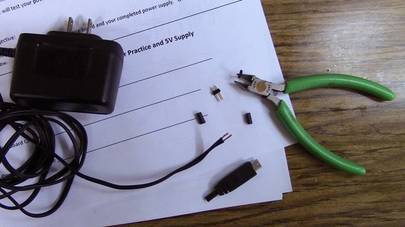
We had a very nice lecture and lab practice on how to use a multimeter this evening. We used a multimeter to measure continuity, resistance, voltage, current and capacitance, etc.

We used a multimeter to find out if two electronic parts are electrically connected. We used the solder board we soldered yesterday for practice. We only test continuity when the device is not powered so we can get the correct reading. Here are some examples of using a multimeter:

Testing electrical continuity:
Continuity is non-directional; it is the same how you place your probes on the device you are testing.
Testing Batteries:
We switched to DC mode when measuring batteries. Direct current voltage is what comes out of batteries.
Here is my 9V battery measured 8.88V with the multimeter. Normally, a brand new one starts out as high as 9.6V then its voltage slowly drops down and drifts away.

Testing Wall Output:
We switch to AC mode for measuring the wall output, alternate current (AC) voltage is what comes out of the wall.
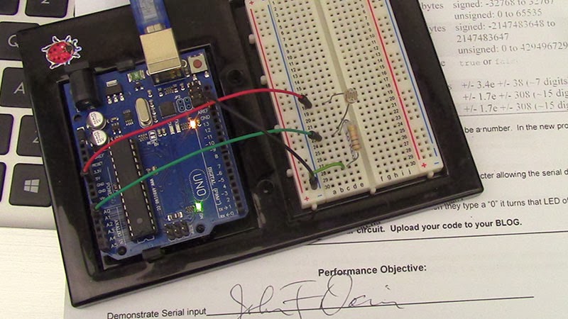
Besides reading the resistor's color coding, I also used a multimeter to measure my resistors before building the circuit.
The amount of current (I) going through a LED is directly proportional to how bright it appears. Whenever using an LED, always have a resistor, it limits the current and will keep the LED from burning out!

Adjusting Brightness:
A potentiometer is a manually adjustable resistor. Used to control the voltage of a circuit. Unlike the resistor you seen in the above circuit, the resistance is fixed. The pot has 3 pins, the resistance between the two outer pins is always the same. The resistance between the middle pin and the left or right pin changes.


Tuesday, January 7, 2014

Day One: Soldering and making a 5V power supply


This is my solder practice board. It is not perfect. A few of them are better than others; some of them have too much of solder, I still need more practice to do a better job. 


Safety always comes first!
Before I chop off the little plug at the end of its wire. I make sure that the AC adapter is not plugged into the wall.


Here is my completed 5V power supply.


I used three Light Emitting Diodes (LEDs) and a 1kΩ resistor to test my power supply. It works. I learned that resistors work either way, it has no polarity. Unlike the resistor, if you place the LED in backwards it won't work because current in a diode flows only one way: it flows from the positive side to the negative side.